There are lots to learn about SMD packages, sizes, marking etc. In the beginning it’s a been confusing, so I’ve tried summarise my own quick intro below.
Integrated circuits (lots of pins!)
The following overview is copied from Microchip selector guide page 38. Click on picture below to get a more readable size.
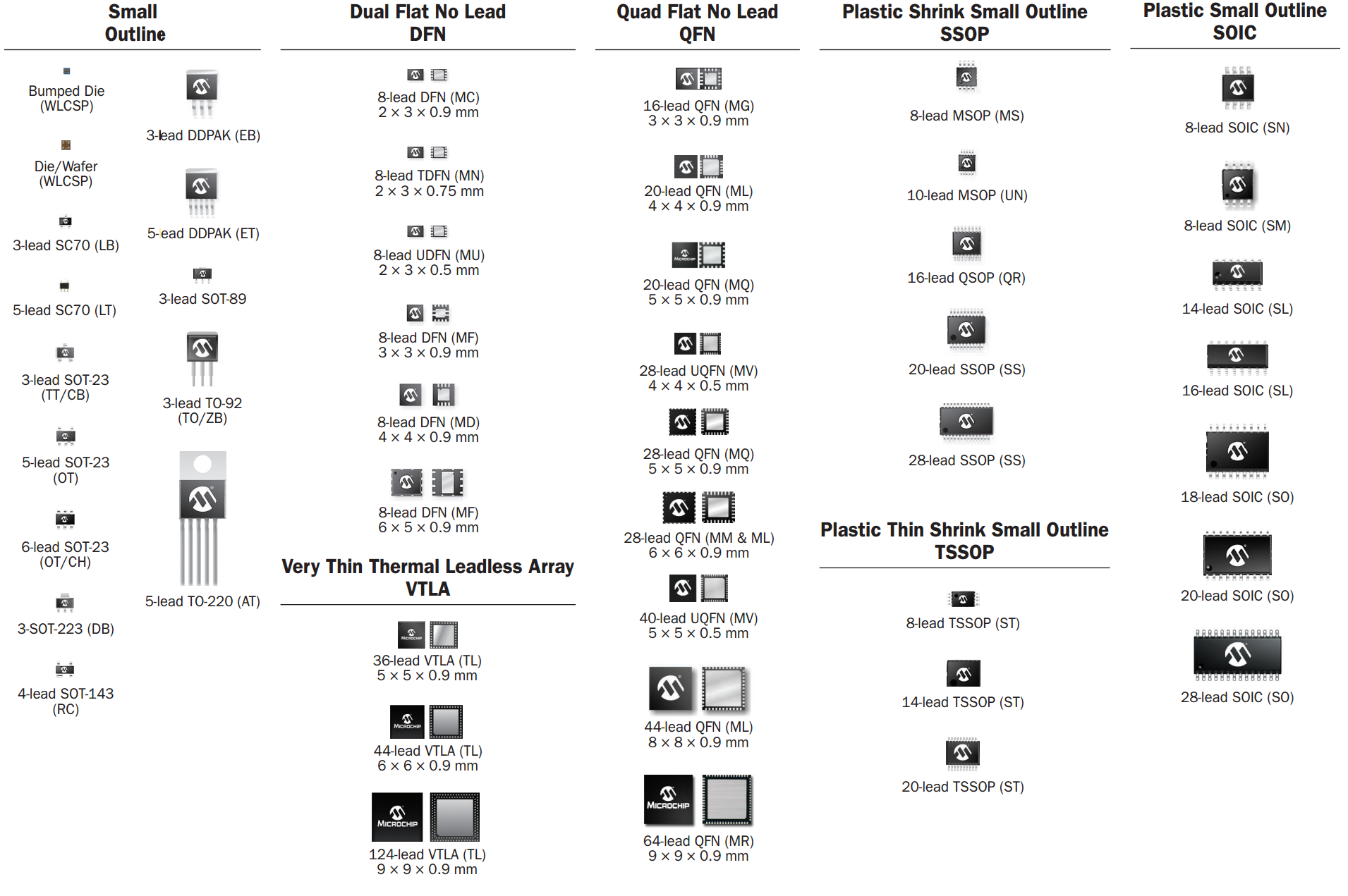
Topline.tv has a good overview where you can easily clik into the various types. Microchip has a PDF with even more data for each type, but normally I don’t need so much details.
SOT23
Comes with various pin combinations and corresponding pin spacing. Refer to topline.tv/SOT.
I.e. SO23-6 has 0.95mm pin spacing while SO23-8 has 0.65mm pin spacing.
All types are typically prefixed or postfixed with a number indicating number if pins. I.e. a 8 pin 8SOT23 is the same as SOT23-8.
QUAD


QFP
QFP (Quad Flat Package) have “gull wing” leads extending from each of the four sides. Versions ranging from 32 to 304 pins with a pitch ranging from 0.4 to 1.0 mm are common. Spesial versions TQFP(thin) and LQFP(low profile) exists.
QFN (no lead)
The QFN package (flat no leads) is similar to the QFP, but the leads do not extend out from the package sides. Also known as micro leadframe (MLF) and SON (small-outline no leads). Some have tiny metal areas available on the side making it possible to hand solder (such as FT800). Others do not, making it more of less impossible to hand solder.

SOIC (SO, SOIC, SOP)
SOIC: (Small-Outline Integrated Circuit), dual-in-line, 8 or more pins, pin spacing 1.27 mm.

TSOP, SSOP, TSSOP, MSOP
Thin Small Outline Package info from Wikipedia. Info from topline: TSSOP • SSOP • TSOP
TSOP (Thin Small-Outline Package). Pin spacing typically 0.5 mm (Type I). Type II pin spacing typically depends on number of pins. 32 pins typically have 1.27mm while larger have 0.8mm ? Type I ICs have the pins on the shorter side and Type II have the pins on the longer side
SSOP (Shrink Small-Outline Package). Pin spacing 0.65 mm, sometimes 0.635 mm (in some cases 0.8 mm). Pad width .22-.38mm.
TSSOP(Thin Shrink Small-Outline package): Pin spacing 0.65mm. Pad width .30mm.
MSOP (Mini Small Outline Package): Pin spacing 0.5mm (10-16pin) and 0.65mm(8 pin).


Tips on how to work with them
Easiest is using breakout boards. Note that 8 pin TSSOP and MSOP have 0.65mm pin spacing and can typically use the same breakout boards such as Adafruit SMT Breakout PCB for SOIC-8, MSOP-8 or TSSOP-8. It has SOIC-8 (1.27mm) on the other side, so they can be used for a lot of 6/8 pin components. You get 6 of these for $5:


If you really want volume, you may try Aliexpress, i.e. 50pcs adapter board SOP8/ SSOP8/ TSSOP8 (smd to dip) 0.65/ 1.27mm pitch for less than $20…
I still don’t have a complete overview over all these packages. But I now tend to focus on pin spacing. If they are 0.65mm or 1.27mm, I can use some of the “standard” breakout boards. Good to go. If they are called SOP/TSOP/SSOP/TSSOP/SOIC…I never remember anyway.
For SOT23 etc. Adafruit have a breakout set for SOT-23, SOT-89, SOT-223 and TO525 for $5, max 6 pins (for more that 6 pins, the 0.65mm breakout boards can probably be used?):


Solder without PCB or breakout ? Picture of 32-pin MQFP chip with manually soldered wires attached for prototyping below:

Other overviews
Another SOP/TSOP/SSOP overview from lapis-semi.com.
Package dimensions from not2fast.com.
Discrete/passive components
Overview pictures from i.e. wikipedia:
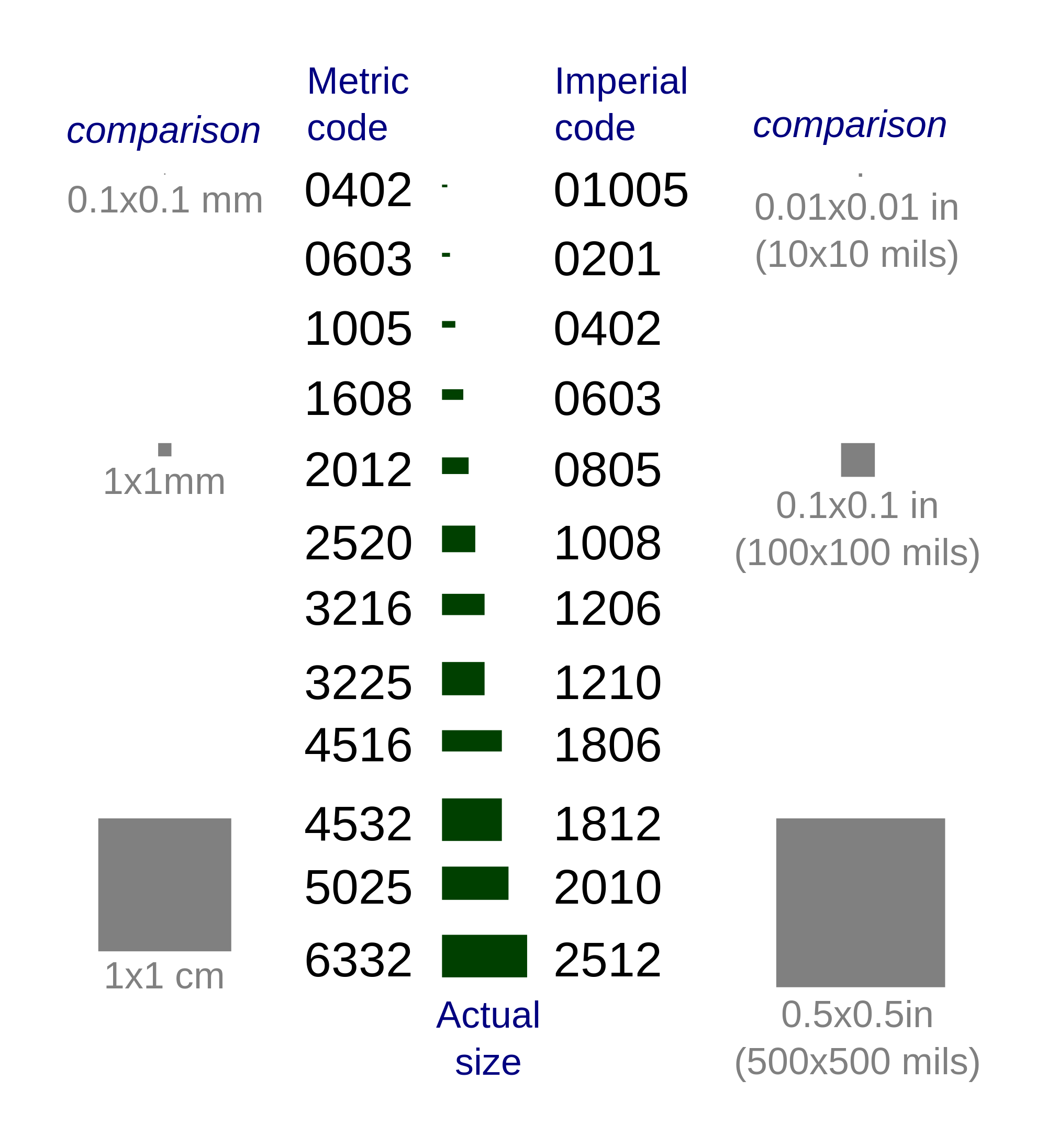

Discrete/passive components such as resistor and capacitors are easier to work with. The most common standard packages relevant for hand soldering are 0603, 0805 and 1206 (named after their physical dimensions in 1/100th of an inch). I think 0805 is the “best” for hobbyists. The 0603 might be a bit cheaper but that is irrelevant for my extremely small volume. Move up to 1206 resistors or larger if you need >1/2 watt.
Value markings
Resistors are typically marked with numbers to indicate value. Normally the last digit is the value multiplier. Example: 292 is 2900 = 2.9Kohm. Read more i.e. here.
Electrolytic and tantalum capacitors are typically marked with their capacitance and working voltage. The voltage and uF can be indicated directly:47 6V is 47μF 6V. Smaller sizes typically use letter to indicate voltage and digit to indicate nF: A 475 means 10V 475 = 10V 4700000pF = 10V 4.7μF.
Ceramic capacitors are typically not marked which makes them hard to identify without meter.
There are a lot of different types to be used for different applications.

Inductors are typically marked with numbers to indicate value. Normally the last digit is the value multiplier. Example: 101 = 100μH

Practical considerations when buying my own SMD components
I’ve bought a INA219 which us available in two packages: SO8 and SOT23-8. Breakout boards are available for both, but SO8/SOIC8(1.27mm pitch) is easier to solder than SOT23-8 (0.65mm). Unfortunately I bought SOT23-8, but that was before I started digging into this (and looking closer now I see that my supplier didn’t have SO8/SOIC7´8 packages available…)
Soldering the damn thing!
There are plenty of instructions out there. I’ll try to add the ones I find best as I go along. For now, start with google or this.

H can some one help clear somthing up for me?i ordered attiny84 qfn 20 pins 5x5x5x5 package etc but they wont fit what i want them to fit they just a bit too small,i read the bom sheet and it said attiny84 qfn/mlf but never said wich package so i ordered the qfn,but they just a tad bit small,so that leavs me to belive that i need the mlf package,so my question is= is the mlf a tad bit bigger than the qfn package same pins etc 5x5x5x5 = 20 pins on bothe packages? it must be the mlf i need,its an eagle schematic and brd file that says attiny84 -qfn/mlf.it should say the exact package as to avoide any confusion
LikeLike
Not sure if I can help you but on page 13 in http://www.atmel.com/Images/8006S.pdf they refer to a package “20-pad, 4 x 4 x 0.8 mm Body, Quad Flat No-Lead/Micro Lead Frame Package (QFN/MLF)”. On page 14 there is a diagram showing the size. No indications there that there are differences between QFN and MLF. Do you have the PCB where the device is to be mounted ?
LikeLike